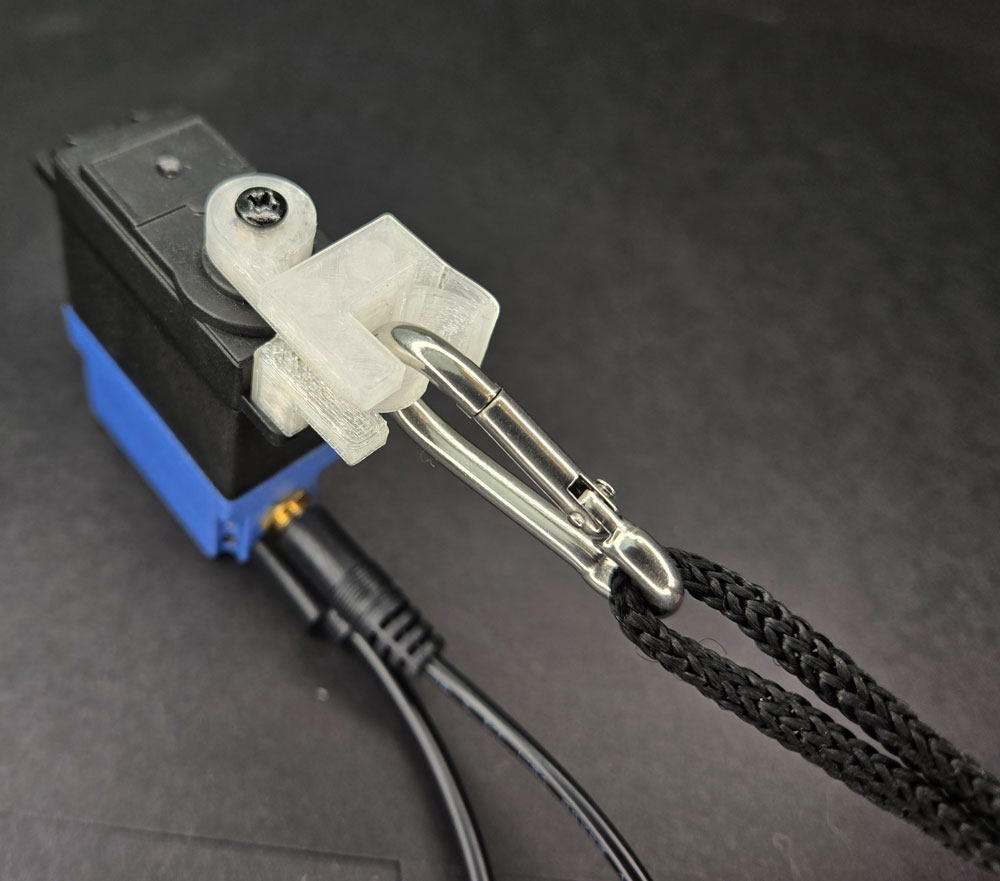
SMART LOCKING: SECURE & RELEASE KIT
LESSON SNAPSHOT
| Kit | Smart Locking: Secure & Release Kit - Student Guide #7 |
|---|---|
| Client | Robert Kim, Age 45 - High school science teacher needing automated carabiner system for securing equipment during outdoor education and lab work |
| Core Concept | Compliant mechanisms and bistable systems; designing for accessibility through automated control |
| Prerequisites | Getting Started with Smart Servo (Guide 1); basic servo programming; experience with mounting systems recommended |
| Student Guide | tinyurl.com/SS-STL-LOCK |
⚠️ Safety Considerations
- Test release mechanism: Without weight before attaching items; ensure carabiner is properly seated before use
- Servo rotation angles: Verify angles prevent unintended releases; supervise when securing items overhead or items that could fall
What This Kit Teaches
Engineering/Design Focus: This kit introduces compliant mechanisms—structures that achieve motion through material flexibility rather than traditional joints or separate springs. Students explore how a single 3D printed piece can function as both rigid structure and flexible spring, learning to optimize servo rotation for minimal movement while achieving functional release.
Human-Centered Design Connection: Robert's need illustrates how fine motor limitations create accessibility barriers in everyday tools. The automated carabiner addresses his specific constraint (inability to pinch traditional carabiner gates) while maintaining the security and quick-release function he needs for outdoor education and lab safety.
Standards at a Glance: Primary domains are HCD, STEL, NGSS (ETS1, Cross-Cutting Concepts), CAD - See page 5 for complete alignment
ESSENTIAL TEACHING MOMENTS
Key concepts worth pausing to discuss during the lesson
Moment 1: Compliant Mechanisms as Integrated Systems
Student Guide Reference: Steps 4-6 (installing Compliant Lock and Carabiner)
Core Idea: A single piece of material can serve multiple functions—providing both rigid structure and spring action—through intentional design of thickness, geometry, and material properties.
Why It Matters: Compliant design reduces manufacturing complexity, eliminates assembly of multiple parts, and creates more reliable mechanisms with fewer failure points. This principle is revolutionizing fields from medical devices to aerospace engineering.
Discussion Prompts to Consider:
- "What would this mechanism look like if we used traditional separate parts instead of a compliant design? How many pieces would we need?"
- "Where have you seen flexible plastic parts that spring back into place in everyday objects? What advantages do those designs have?"
- "Why might a single-piece design be especially valuable for Robert's outdoor use case?"
Watch For: Students may initially not recognize that the spring action comes from the material itself rather than a separate spring component. Use comparison with traditional carabiners to highlight the difference.
Moment 2: Bistable Systems and State Control
Student Guide Reference: Steps 6-7 (installing and testing release mechanism)
Core Idea: The mechanism exists in two stable states (locked and unlocked), with the servo providing controlled transition between states rather than continuous holding force.
Why It Matters: Bistable designs are energy-efficient because they don't require constant power to maintain position. Understanding state-based design prepares students for more complex control systems and helps them reason about when mechanisms should "hold" versus "transition."
Discussion Prompts to Consider:
- "Once the carabiner is locked, does the servo need to keep using power? Why or why not?"
- "What happens if power is lost while equipment is secured? Is this a safety feature or concern for Robert's use case?"
- "Can you think of other devices that have distinct 'locked' and 'unlocked' states?"
Extension Opportunity: Discuss fail-safe versus fail-secure design philosophy. Should the mechanism default to locked or unlocked if power fails? How does Robert's specific context (lab safety versus outdoor equipment) influence this decision?
Moment 3: Optimization Through Minimal Movement
Student Guide Reference: Step 8 (optimizing rotation angles)
Core Idea: Effective mechanism design often requires the minimum motion necessary to achieve the desired result, reducing energy consumption, increasing speed, and minimizing wear.
Why It Matters: Over-rotation wastes energy, slows response time, and can introduce mechanical stress. Learning to optimize for "just enough" movement develops engineering judgment about efficiency and precision.
Discussion Prompts to Consider:
- "How did you determine the minimum rotation angle needed? What happened if you went too small?"
- "What are the advantages of rotating only 10-15 degrees instead of the full 90-degree range the servo can provide?"
- "How might weather conditions (cold temperatures making materials more brittle, or heat making them more flexible) affect the optimal rotation angle?"
Demo/Visual Aid Suggestion: Show the carabiner release at different rotation angles using slow-motion video or step-by-step demonstration. Have students predict the minimum angle before testing.
Moment 4: Designing for Context and Constraints
Student Guide Reference: Client profile and "THE BIGGER PICTURE" section
Core Idea: Robert's C6 spinal cord injury leaves him with good wrist control but limited fine motor function, making traditional pinch-and-squeeze mechanisms inaccessible while larger button controls remain usable.
Why It Matters: Effective assistive technology design requires deep understanding of specific abilities and limitations, not just general categories of disability. The same injury level affects different people differently, and environmental factors (cold hands, gloves) create situational constraints.
Discussion Prompts to Consider:
- "Why is a carabiner specifically challenging for Robert, while he can operate larger controls?"
- "How does his role as an outdoor education teacher create additional requirements beyond just 'opening a carabiner'?"
- "What environmental factors in outdoor settings might affect how this device needs to perform?"
- "If we were adapting this for someone with different physical capabilities, what aspects of the design might need to change?"
MATERIALS & PREPARATION
What Students Need
- Kit components listed in student guide Step 1:
- Hook Horn
- Compliant Lock
- Carabiner
- Tools and components from previous kits (student guide Step 2):
- Smart Servo
- Phillips Screwdriver
- Mounting Screws
- Test Button
- Power source (battery pack or USB connection)
- Safety equipment: Clear workspace for testing mechanism
What You Need to Prepare
- Pre-build one kit to understand carabiner seating process and identify optimal rotation angles for release
- Test code modifications to determine reasonable angle ranges (typically 10-20 degrees from lock position)
- Prepare visual aids for compliant mechanisms—gather examples of living hinges from everyday objects (flip-top bottles, snap-fit containers)
- Review student guide pages on compliant design principles and material properties
- Set up demonstration station with traditional carabiner for comparison
- Prepare test weights (water bottles, tools) appropriate for testing once mechanism is verified safe
- Choose assessment approach (see page 4)
- Select extension activities if time allows (see page 4)
Quick Troubleshooting Reference
| If students struggle with... | First, check... | Then try... |
|---|---|---|
| Carabiner won't stay locked | Whether carabiner is fully pushed past the spring's redirect point (Position B in diagram) | Press more firmly until spring clearly holds carabiner against Hook Horn; check that spring hasn't been over-flexed |
| Release mechanism not working | Servo rotation direction and angle—needs to rotate away from carabiner | Adjust code to increase rotation angle slightly; verify Hook Horn is properly secured to spline |
| Servo making squealing noise | Over-rotation or mechanism binding | Reduce rotation angle; check that Compliant Lock isn't over-tightened with mounting screws |
| Compliant Lock feels too rigid | Material temperature (cold plastic is less flexible) | Allow mechanism to warm to room temperature; verify correct orientation during assembly |
1. ENGAGE: Understanding the Challenge
How do Robert's specific physical capabilities affect his interaction with traditional carabiners?
Learning Focus: Students understand Robert's specific physical capabilities and constraints, and recognize how traditional carabiner design creates accessibility barriers.
Suggested Activities
Client Introduction:
- Have students read Robert's client profile carefully
- Consider: Physical simulation activity—have students try operating a traditional carabiner while wearing thick winter gloves or with limited finger movement (using only thumb and wrist)
- Discuss: What specific motion does a traditional carabiner require? Why is this challenging with limited fine motor control but good wrist strength?
Problem Framing:
- Guide students to articulate: "Robert needs a way to securely attach and release equipment without pinching motions because his C6 spinal cord injury limits fine motor function in his hands"
- Explore context: Why is this particularly important for his role as an outdoor education teacher? What are the safety implications in lab and field settings?
- Preview: How might automated control transform accessibility of standard equipment?
Connection to Real-World Context:
- Discuss the spectrum of spinal cord injuries and how specific injury levels affect different capabilities
- Consider situational limitations that affect everyone: cold hands, wearing gloves, holding something in the other hand
Formative Assessment Ideas:
- Can students explain why wrist control alone isn't sufficient for traditional carabiners?
- Do they identify both safety and independence dimensions of the challenge?
- Can they distinguish between Robert's baseline capabilities and environmental factors that create additional constraints?
Standards Connection: Primary: HCD #1 (Problem Framing—analyzing accessibility barriers), STEL 1Q (Research to inform design for specific user needs), STEL 7S (Human factors in design), NGSS ETS1 (Define engineering problem with criteria and constraints)
2. EXPLORE: Building & Discovering
How do material properties create spring action in a single-piece design?
Learning Focus: Students develop assembly skills with compliant mechanisms and discover how material flexibility creates spring action in a single-piece design.
Facilitation Approach
Before Building
- Students complete Steps 1-2 (identify new components, gather previous kit items)
- Consider: Prediction activity—"Examine the Compliant Lock. Where do you think flexibility happens? What makes this different from a metal spring?"
- Demonstrate proper carabiner seating technique (Steps 4-6 require firm pressure to overcome spring resistance)
- Review safety: Test mechanism thoroughly before attaching any weighted items
During Building
- Students follow assembly instructions in Steps 3-7
- Use Essential Teaching Moments (page 2) as strategic pause points:
- After Step 4: Pause to examine how the Compliant Lock flexes (Moment 1)
- After Step 6: Discuss the locked state and what maintains it (Moment 2)
- During Step 8: Guide optimization thinking (Moment 3)
- Circulate to observe: Are students recognizing the spring action in the material itself? Are they seated the carabiner fully before testing?
- Encourage comparison with traditional carabiners if available
Testing Phase
- Guide systematic observation: "What's the minimum angle that reliably releases? What happens with larger angles?"
- Consider: Data collection about rotation angles and release reliability across different carabiner positions
- Emphasize Step 8 optimization—this is engineering judgment, not arbitrary adjustment
Formative Assessment Ideas:
- Can students identify where flexibility occurs in the Compliant Lock?
- Do they understand that the locked state doesn't require continuous servo power?
- Are they approaching angle optimization systematically rather than randomly?
- Can they explain the relationship between rotation angle, release speed, and energy efficiency?
Standards Connection: Primary: CAD 1.2 (Assembly with compliant components), CAD 2.4 (Geometric analysis of clearances and motion), NGSS Practice 3 (Planning and carrying out investigations—systematic testing), STEL 2M (Systems thinking—inputs, processes, outputs)
3. EXPLAIN: Making Sense of Concepts
How do compliant mechanisms integrate multiple functions into single components?
Learning Focus: Students connect hands-on experience with compliant mechanisms to broader engineering principles about material properties, integrated design, and bistable systems.
Suggested Sequence
Process the Experience
- Reflection: "What surprised you about how the lock worked? How is this different from mechanisms with separate springs?"
- Use completed assembly to introduce vocabulary: compliant mechanism, living hinge, bistable system, yield strength, elastic deformation
- Have students identify the specific features that create spring action (thickness variations, geometry of curves)
Explore Core Concepts
- Draw heavily from "THE BIGGER PICTURE" section in student guide
- Compliant Design Principles: Use the Compliant Lock as reference to discuss how single pieces replace multiple parts. Demonstrate with comparison objects (flip-top bottles, snap-fit lids).
- Material Properties and Limits: Explain yield strength concept—materials can bend repeatedly within limits but break if pushed too far. Connect to why thickness matters in the design.
- Bistable Systems: Diagram the two stable states (locked/unlocked) and the transition between them. Discuss energy implications of not requiring power to maintain locked state.
- Extend to real-world applications: medical devices (sterilization benefits), aerospace (deployable structures), consumer products (reducing manufacturing cost)
Teaching Strategies to Consider
- Use think-pair-share to compare compliant mechanisms with traditional multi-part assemblies
- Have students sketch and label the areas of flex in the Compliant Lock
- Create comparison chart: advantages and disadvantages of compliant design versus traditional mechanisms
- Show videos or images of complex compliant mechanisms (NASA deployable arrays, compliant robot grippers)
Connect to User Needs
- Discuss: How does the reliability of single-piece design benefit Robert in outdoor conditions?
- Analyze design trade-offs: Compliant mechanisms may have limited range or force, but offer simplicity and reliability
- Consider customization: How might material choice or thickness adjustment optimize for Robert's specific equipment and environment?
Formative Assessment Ideas:
- Can students define compliant mechanism and identify examples beyond the kit?
- Can they explain why the material doesn't break despite repeated bending?
- Do they connect bistable design to energy efficiency and fail-safe behavior?
- Can they articulate the engineering trade-offs between compliant and traditional mechanisms?
Standards Connection: Primary: CAD 1.4 (Explain technical solutions using appropriate vocabulary), HCD #2 (Communicate technical concepts to stakeholders), NGSS Cross-Cutting Concepts (Structure and Function—how design enables spring action; Cause and Effect—material properties create motion)
4. ELABORATE: Extension & Application
How can compliant mechanism principles transfer to new design challenges?
Learning Focus: Students apply understanding of compliant mechanisms and automated control to new contexts, optimize designs for specific conditions, or explore related accessibility challenges.
Extension Menu
Choose based on available time, student readiness, and learning priorities
Option A: Environmental Adaptation Analysis
What Students Do: Analyze how temperature, moisture, or material choices would affect the mechanism's performance in Robert's outdoor education context, then propose modifications
Time Estimate: 30-45 minutes
Skills Developed: Engineering analysis, material science reasoning, design for extreme conditions
Good For: Reinforcing connection between material properties and real-world performance; introducing environmental engineering considerations
Standards: STEL 3F (Apply to another setting—indoor lab vs outdoor field use), STEL 5G (Evaluate trade-offs), HCD #8 (Iteration based on environmental testing)
Option B: Compliant Mechanism Design Challenge
What Students Do: Design a new compliant mechanism for a different function (door latch, tool holder, adjustable clip) using similar principles of living hinges and material flexibility
Time Estimate: 60-90 minutes
Skills Developed: Transfer of compliant design principles, CAD modeling of flexible features, iterative prototyping
Good For: Deep conceptual understanding and creative application of compliant design principles
Standards: STEL 3H (Transfer knowledge to new applications), CAD 3.2 (Parametric modeling of flexible features), HCD #3 (Innovation process—divergent and convergent thinking)
Option C: Bistable System Programming Extension
What Students Do: Modify code to add features like double-press confirmation to prevent accidental releases, timed auto-lock, or status feedback through LED color changes
Time Estimate: 45-60 minutes
Skills Developed: Computational thinking, state-based programming logic, user interface design
Good For: Technology integration and programming practice; exploring fail-safe design
Standards: CSTA (Control structures and conditionals), STEL 8J (Control technological systems), HCD #4 (Risk assessment—preventing accidental releases)
Option D: Accessibility Audit and Transfer
What Students Do: Identify other standard equipment or tools with accessibility barriers similar to traditional carabiners (screw-top bottles, door locks, light switches) and propose how automated control could address them
Time Estimate: 45-60 minutes
Skills Developed: Accessibility analysis, analogical reasoning, identifying design barriers
Good For: Developing empathy and systems-level thinking about accessibility; preparing for future assistive technology projects
Standards: STEL 1M (Creative problem-solving), HCD #1 (Problem framing from multiple perspectives), STEL 4N (Analyze how technology changes interaction)
Option E: Research and Presentation—Compliant Mechanisms in Industry
What Students Do: Research real-world applications of compliant design (medical devices, aerospace, consumer products) and present findings on why engineers chose compliant solutions
Time Estimate: 60-90 minutes
Skills Developed: Research skills, technical communication, connecting classroom concepts to professional engineering
Good For: Cross-curricular ELA integration; understanding engineering decision-making
Standards: NGSS Practice 8 (Obtaining and evaluating information), HCD #5 (Knowledge development), STEL 6C (Historical solutions research)
5. EVALUATE: Demonstrating Learning
How can students demonstrate mastery of compliant mechanism principles and user-centered design?
Learning Focus: Students demonstrate understanding of compliant mechanisms, bistable systems, and user-centered design through building, explanation, and application.
Recommended Assessment Approach
Performance Demonstration with Technical Explanation
What Students Do: Successfully build and optimize the automated carabiner system, then explain how the compliant mechanism functions and how the design serves Robert's specific needs
What You Assess: Assembly accuracy (carabiner properly seated and reliably locked), code optimization (minimal rotation angle), technical explanation (compliant mechanism principles), user-centered reasoning (connection to Robert's constraints)
Evidence: Completed functional device + verbal or written explanation addressing both mechanical principles and accessibility context
Time Required: Ongoing during build + 5-7 minutes for explanation per student/group
Best For: Authentic demonstration combining hands-on skills with conceptual understanding
Alternative Assessment Options
Option 2: Compliant Design Portfolio
Students document their building process, optimization decisions, and conceptual understanding through annotated photos, sketches showing flex zones, code with comments explaining optimization logic, and written reflection connecting compliant design to Robert's needs. Good for process-focused assessment and students who communicate better through writing than presentation.
Option 3: Design Proposal for Improved Version
Students propose modifications to the mechanism for specific conditions (extreme cold, one-handed operation, attachment to wheelchair frame) with justified reasoning based on compliant design principles and Robert's context. Assesses deeper conceptual understanding and design thinking.
Reflection Prompts
Choose 2-3 based on your learning priorities
- Process: What was most challenging about optimizing the release mechanism? What strategy helped you find the minimum rotation angle?
- Concept: Explain compliant design to someone who hasn't seen this kit. Why is using material flexibility instead of separate springs valuable in engineering?
- Impact: How does this automated carabiner specifically address Robert's needs in ways a traditional carabiner cannot? What aspects of his situation made this solution appropriate?
- Transfer: Where else have you noticed single-piece designs that flex rather than using separate springs or hinges? Why might engineers choose that approach?
- Trade-offs: What are the limitations of compliant mechanisms compared to traditional multi-part designs? When might traditional approaches be better?
Standards Connection: Assessment should provide evidence of: CAD 1.1-1.4 (Technical vocabulary, assembly skills, documentation, communication), HCD #2, #8, #9 (Stakeholder communication, iteration through optimization, design documentation), NGSS Practices (Constructing explanations, designing solutions)
CONNECTIONS & CONTEXT
Learning Sequence
What Students Already Know (from previous kits):
Basic servo control and programming (Guide 1); mounting systems and positioning (Guide 2); mechanical systems and motion conversion (Guides 3-6); systematic testing and optimization; human-centered problem framing; working with client profiles
What's New in This Kit:
Compliant mechanisms and living hinges; bistable systems; material properties (yield strength, elastic deformation); single-piece integrated design replacing multi-part assemblies; optimization for minimal movement; fail-safe considerations in control systems
Where This Leads (in future kits):
Low-Fi Prototyping Kit (Guide 8) will build on quick-release concepts for rapid exploration; Dual Servo Kit (Guide 9) introduces coordinating multiple systems; Pan & Tilt Kit (Guide 10) extends multi-axis control; concepts about material properties and optimization inform all future advanced projects
Cross-Curricular Connections
Mathematics
Optimization problems (finding minimum angle that achieves desired result); geometric reasoning about rotation angles and arc length; ratio and proportion in understanding how rotation translates to linear carabiner movement; data collection and analysis during testing phase
Science
Material properties and elasticity (yield strength, elastic vs plastic deformation); potential energy storage in flexed materials; force and motion in servo actuation; physics of bistable systems and energy states
Social Studies
Americans with Disabilities Act (ADA) and accessibility legislation; history of assistive technology development; discussion of how design choices affect inclusion and participation in activities like outdoor education
English/Language Arts
Technical writing in optimization documentation; persuasive writing in design proposals for modified versions; reading comprehension of technical material in "THE BIGGER PICTURE" section; presenting technical explanations to non-technical audiences
Additional Resources
For Teachers
- Student Guide: Available at tinyurl.com/SS-STL-LOCK
- 3D Printing Files: tinyurl.com/SS-STL-LOCK
- Code Snippets and Reset: tinyurl.com/SmartServoSnips
- Compliant Mechanisms Resources: Search "living hinge design principles" or "compliant mechanism examples" for visual aids and videos
For Students
- Assembly: Detailed instructions in student guide Steps 1-8
- Concepts: "THE BIGGER PICTURE" section explaining compliant design, material properties, and applications
- Code Support: Original factory code available at tinyurl.com/SmartServoSnips for reset if needed
- Troubleshooting: Reference guide on page 3; student guide diagrams for carabiner seating
Extension Reading/Resources
- NASA compliant mechanisms for space applications (deployable solar arrays, antennae)
- Medical device design using compliant mechanisms for sterilization benefits
- Videos demonstrating compliant robot grippers and soft robotics
- Articles about spinal cord injury levels and their specific effects on hand function
- Outdoor education and adaptive recreation programs
APPENDIX
COMPLETE STANDARDS ALIGNMENT
CAD Competencies
| Code | Competency | Where Addressed | How to Emphasize |
|---|---|---|---|
| CAD 1.1 | Technical vocabulary | Phase 2 (Building—compliant lock assembly), Phase 3 (Explain—material properties) - Use Teaching Moment #1 to introduce living hinge, yield strength, bistable system | Have students create labeled diagrams identifying flex zones; develop vocabulary reference sheet; use terms consistently in explanations |
| CAD 1.2 | Assembly/fabrication | Phase 2 (Building) - Steps 3-7 require careful technique, especially carabiner seating | Demonstrate proper seating technique; pause to observe student approaches; assess whether carabiner is fully locked before moving to testing |
| CAD 1.3 | Technical documentation | Phase 5 (Evaluate) - Portfolio option requiring optimization process documentation | Provide templates for documenting angle testing; emphasize importance of recording what works and doesn't; model annotation of code changes |
| CAD 1.4 | Explain technical solutions | Phase 3 (Explain), Phase 5 (Evaluate) - Technical explanations of compliant mechanism function | Use sentence frames: "The [part] functions by..."; require connection between material properties and performance; practice explaining to non-technical audiences |
| CAD 2.4 | Geometric analysis | Phase 2 (Testing—Step 8 optimization), Teaching Moment #3 - Understanding rotation angles and mechanical clearances | Guide systematic testing of angles; discuss relationship between rotation and carabiner path; use visual aids showing motion geometry |
| CAD 3.1 | CAD fundamentals | Extension Option B - Designing new compliant mechanisms | If extending to CAD design, emphasize thickness variations and curve geometry that create flexibility; model how to design living hinges |
| CAD 3.2 | Parametric modeling | Extension Option B - Creating adjustable compliant features in CAD | Teach how to parameterize thickness or curve radius to adjust flexibility; demonstrate testing different parameter values |
| CAD 3.3 | Assembly modeling | Phase 2 (Building) - Understanding how Hook Horn, Compliant Lock, and Carabiner interact | Discuss clearances and interaction between parts; consider creating exploded view diagrams showing assembly sequence |
| CAD 4.2 | 3D Printing | Throughout - All components are 3D printed; compliant features require specific printing considerations | Discuss how print orientation affects flexibility; explain why thin sections print differently; connect layer direction to flex behavior |
CSTA Computer Science Standards
| Code | Standard | Where Addressed | How to Emphasize |
|---|---|---|---|
| Computing Systems: Devices | Describe computing device parts and functions | Phase 2 (Testing) - Understanding servo as actuator, microcontroller as controller, button as input | Create system diagrams showing information flow from button press through code execution to servo movement |
| Computing Systems: Hardware & Software | Model hardware and software system interactions | Phase 2, Phase 3 - Connecting code changes to physical release behavior | Explicitly trace the path: button press → code execution → servo angle change → Hook Horn rotation → carabiner release |
| Computing Systems: Hardware & Software | Design projects combining hardware and software | Throughout - Integration of programming and mechanical design | Emphasize that both code optimization (Step 8) and mechanical setup affect performance; discuss interdependence |
| Computing Systems: Troubleshooting | Determine solutions to hardware/software issues | Phase 2 (Building/Testing) - Troubleshooting release mechanism, optimization challenges | Guide systematic approach: Is it mechanical (carabiner not seated)? Is it code (wrong angle)? Is it electrical (connection issue)? |
| Algorithms & Programming: Control | Programming control structures | Phase 2 (Step 8 optimization) - Modifying servo angle values in code | Discuss how changing numerical values in code creates different physical behaviors; practice precise control |
| Algorithms & Programming: Control | Complex control structures | Extension Option C - Adding double-press confirmation or timed features | Introduce conditional logic for safety features; use state variables to track locked/unlocked status |
HCD Skills & Tools
| Code | Skill/Tool | Where Addressed | How to Emphasize |
|---|---|---|---|
| HCD #1 | Problem Framing | Phase 1 (Engage) - Analyzing Robert's specific capabilities and constraints | Use multiple perspectives: What can Robert do? What can't he do? What environmental factors matter? Distinguish between injury-based and situational limitations |
| HCD #2 | Engineering Communication | Phase 3 (Explain), Phase 5 (Evaluate) - Connecting compliant mechanism function to user benefits | Practice explaining technical features in user-friendly language; require students to describe "how this helps Robert" not just "how this works" |
| HCD #4 | Risk Assessment | Teaching Moment #2, Extension Option C - Discussing fail-safe behavior and preventing accidental releases | Analyze: What happens if power fails? If button is accidentally pressed? Guide thinking about safety in different scenarios |
| HCD #5 | Knowledge Development | Phase 3 (Explain) - Learning about compliant mechanisms and material properties | Make learning process visible; discuss how engineers acquire specialized knowledge; connect to student guide's "THE BIGGER PICTURE" as expert resource |
| HCD #6 | Stakeholder Dialogue | Phase 1 (Engage), Teaching Moment #4 - Understanding Robert's needs through his profile | Role-play follow-up questions students would ask Robert; practice active listening and clarifying requirements |
| HCD #8 | Iteration Cycles | Phase 2 (Step 8 optimization) - Systematic testing and refinement of rotation angle | Frame optimization as iteration: test, observe result, adjust, retest; emphasize that "perfect" often comes through refinement |
| HCD #9 | Design Documentation | Phase 5 (Evaluate) - Portfolio option documenting process and decisions | Teach why documentation matters for future improvements; model clear recording of testing results and reasoning |
| HCD Tool 1.1 | Interview | Phase 1 (Engage) - Discussing what questions to ask Robert | Generate list of follow-up questions about specific equipment, usage context, and preferences; practice empathetic inquiry |
| HCD Tool 1.2 | Problem Statement | Phase 1 (Engage) - Articulating Robert's need | Use template: "Robert needs [automated carabiner control] to [secure/release equipment] because [C6 injury limits pinching motions]" |
| HCD Tool 2.1 | Criteria & Constraints | Throughout - Understanding servo torque limits, rotation ranges, and Robert's specific requirements | Create explicit list: Criteria (secure hold, reliable release, one-handed operation) vs Constraints (servo torque, rotation angle, material flexibility limits) |
| HCD Tool 3.1 | Sketching | Extension Option B - Designing new compliant mechanisms | Encourage quick sketches before CAD work; use sketching to explore different living hinge geometries |
| HCD Tool 4.3 | Proof of Concept | Phase 2 (Building and Testing) - Creating functional prototype | Discuss purpose of prototypes: testing feasibility, revealing problems, communicating ideas to stakeholders |
| HCD Tool 5.2 | Results Analysis | Phase 2 (Step 8 optimization) - Systematic testing and drawing conclusions | Guide data collection about different angles; teach drawing conclusions from testing rather than guessing |
NGSS Science & Engineering Practices
| Code | Practice | Where Addressed | How to Emphasize |
|---|---|---|---|
| Practice 1 | Define design problems | Phase 1 (Engage) - Clarifying Robert's accessibility challenge with criteria and constraints | Frame as engineering problem: What needs to work? What are the limits? What defines success? |
| Practice 2 | Develop and use models | Phase 2 (Building), Phase 3 (Explain) - Physical model demonstrates compliant design principles | Discuss how physical model helps understand abstract concepts like yield strength and elastic deformation |
| Practice 3 | Planning and carrying out investigations | Phase 2 (Step 8 optimization) - Systematic testing of rotation angles | Guide structured testing: prediction, test, observation, conclusion; emphasize systematic approach over trial-and-error |
| Practice 5 | Using mathematics and computational thinking | Extension Option D - Calculating forces, angles, or material stress | If extending to calculations, make quantitative thinking visible; connect numbers to physical meaning |
| Practice 6 | Constructing explanations | Phase 3 (Explain) - Explaining how compliant mechanism creates spring action through material flex | Require cause-and-effect reasoning: "The thin section flexes because... which causes... resulting in spring action" |
| Practice 8 | Obtaining, evaluating, and communicating information | Extension Option E - Research on compliant mechanisms in industry | Evaluate source quality; synthesize information from multiple sources; present technical findings clearly |
NGSS Core Ideas
| Code | Core Idea | Where Addressed | How to Emphasize |
|---|---|---|---|
| ETS1 | Engineering Design | Throughout - especially Phase 1 (problem definition), Phase 2 (prototyping), Phase 4 (optimization) | Emphasize iterative process; connect optimization in Step 8 to engineering practice of refinement |
| ETS2 | Links Among Engineering, Technology, Science, and Society | Phase 1 (Client context), Teaching Moment #4, Extension Option D | Discuss how spinal cord injury research informs assistive technology design; explore how automated control technology enables participation in activities like outdoor education |
NGSS Cross-Cutting Concepts
- Cause and Effect: Phase 2, 3 - Material thickness and geometry cause flex behavior; servo rotation causes carabiner release; temperature affects material flexibility
- Systems and System Models: Phase 2, 3 - Understanding device as integrated system where mechanical, electrical, and material properties interact
- Structure and Function: Phase 3 - How living hinge geometry enables spring function; how material properties determine performance limits
- Stability and Change: Teaching Moment #2 - Bistable system maintains stable locked state until energy is applied to transition to unlocked state
- Energy and Matter: Phase 3 - Potential energy stored in flexed material; energy efficiency of bistable design that doesn't require continuous power
STEL Standards
| Code | Standard | Where Addressed | How to Emphasize |
|---|---|---|---|
| STEL 1J | Develop innovative products solving problems | Throughout - Creating automated carabiner for Robert's specific accessibility needs | Frame as innovation: replacing manual manipulation with automated control; emphasize novelty of solution |
| STEL 1M | Apply creative problem-solving | Extension Options B, D - Designing new compliant mechanisms or identifying other applications | Encourage divergent thinking about other tools with accessibility barriers; support creative mechanism designs |
| STEL 1Q | Conduct research to inform design | Phase 1 (Engage), Extension Option E - Understanding user needs and existing compliant mechanism applications | Make research purposeful: What do we need to know about Robert? About material properties? About existing solutions? |
| STEL 2M | Differentiate inputs, processes, outputs, feedback | Phase 2, 3 - Button input, code processing, servo output, locked/unlocked state as feedback | Create explicit system diagram; label each component's role; discuss how system provides feedback to user |
| STEL 2O | Create open-loop system requiring human intervention | Throughout - Human must press button to initiate release | Discuss why automated carabiner remains open-loop (user-initiated) rather than automatic; connect to safety and control |
| STEL 2S | Defend design decisions | Phase 2 (Step 8 optimization), Phase 5 (Evaluate) - Justifying rotation angle choices | Require evidence-based reasoning: "I chose X degrees because testing showed..." |
| STEL 2T | Demonstrate modeling types | Phase 2 (Building—physical prototype), Extension Option B (CAD modeling) | Discuss how different model types serve different purposes; physical tests function while CAD explores variations |
| STEL 2W | Select resources balancing factors | Extension Option A - Analyzing material choices for outdoor conditions | Discuss trade-offs: durability vs flexibility, cost vs performance, weight vs strength |
| STEL 2X | Cite examples of criteria and constraints | Phase 1 (Engage), throughout - Servo torque limits, rotation range, material yield strength, Robert's capabilities | Make constraints visible and recurring; show how they shape every design decision |
| STEL 3B | Demonstrate how simple technologies combine into complex systems | Phase 3 (Explain) - Microcontroller + servo + compliant mechanism + button = functional assistive device | Explicitly show how integrating simple components creates sophisticated capability |
| STEL 3D | Employ technology to solve problems not otherwise solvable | Teaching Moment #4 - Technology enables Robert to use carabiners despite physical limitations | Emphasize empowerment: technology creating access where manual operation isn't possible |
| STEL 3F | Apply product/system to another setting | Extension Options A, D - Adapting mechanism for different environments or applying automated control to other tools | Discuss what changes (environmental factors, specific equipment) and what stays the same (core principle of automated control) |
| STEL 3H | Transfer knowledge to new applications | Extension Option B - Applying compliant design principles to new mechanisms | Make principle extraction explicit: "What did we learn about living hinges that could apply elsewhere?" |
| STEL 4K | Examine positive and negative effects of technology | Phase 1, 3 - Technology enabling independence (positive) while considering dependence on power/maintenance (limitation) | Balance enthusiasm with realistic assessment; discuss what happens if technology fails |
| STEL 4N | Analyze how technology changes human interaction | Teaching Moment #4 - Automated control changing how Robert interacts with equipment and participates in outdoor education | Discuss broader implications: How does assistive technology affect participation, independence, and inclusion? |
| STEL 5G | Evaluate trade-offs and impacts | Extension Option A, Phase 3 - Material flexibility vs durability; rotation speed vs safety; complexity vs reliability | Teach that engineering always involves trade-offs; practice articulating competing priorities |
| STEL 6C | Research historical solutions for needs | Extension Option E - Evolution of assistive carabiner solutions or compliant mechanism development | Connect current project to historical progression of both assistive technology and compliant design |
| STEL 7Q | Apply design process to solve problems | Throughout - Following human-centered design process from problem definition through testing | Make design process steps visible; emphasize that engineering follows structured methodologies |
| STEL 7S | Create solutions applying human factors | Throughout - especially Teaching Moment #4 - Design specifically addressing Robert's physical capabilities and limitations | Center human factors in every decision: "How does this choice affect Robert's experience and capability?" |
| STEL 7Z | Apply human-centered design principles | Throughout - Empathy (understanding Robert), iteration (optimization), user testing perspective | Explicitly name HCD principles as they're applied; connect to broader HCD framework |
| STEL 8J | Use devices to control technological systems | Throughout - Button controlling servo through programmed microcontroller | Discuss control system hierarchy: human → button → code → servo → mechanism |
SAMPLE ASSESSMENT RUBRIC
Performance Demonstration with Technical Explanation
| Criterion | Developing | Proficient | Advanced |
|---|---|---|---|
| Assembly Accuracy | Device assembled but carabiner doesn't reliably lock or release mechanism doesn't function consistently | Device fully assembled with carabiner properly seated and reliable lock/release function | Device assembled with precision; carabiner seats smoothly; mechanism shows consistent, optimized performance across multiple tests |
| Code Optimization | Uses default rotation angles without modification; mechanism works but isn't optimized | Successfully modifies code to find reduced rotation angle that reliably releases carabiner | Systematically tests multiple angles with documentation; achieves minimal rotation (10-20 degrees) with reliability; explains optimization reasoning |
| Compliant Mechanism Understanding | Describes that mechanism has spring but unclear about how it works; may confuse with separate spring component | Correctly explains that Compliant Lock material itself provides spring action through flexibility; identifies where flex occurs | Explains compliant design with technical vocabulary (living hinge, yield strength); connects geometry and thickness to flex behavior; compares to traditional multi-part mechanisms |
| Bistable Systems Understanding | Recognizes locked and unlocked states but unclear about what maintains them | Explains that locked state is maintained by spring force without continuous servo power; understands servo causes transition between states | Analyzes energy efficiency of bistable design; discusses fail-safe implications of power loss; connects to broader applications of bistable systems |
| User-Centered Reasoning | Mentions that device helps Robert but limited connection to specific needs | Clearly connects automated control to Robert's inability to perform pinching motions; identifies how device addresses his C6 injury limitations | Analyzes specific capabilities (good wrist control) and limitations (fine motor function); discusses environmental factors (gloves, cold); proposes context-specific optimizations (equipment types, mounting considerations) |
| Technical Communication | Explanation uses everyday language; struggles with technical terms; unclear connections between concepts | Uses key technical terms appropriately (compliant mechanism, bistable, servo control); logical explanation of how mechanism functions | Precise technical vocabulary used naturally; clear cause-and-effect explanations; effectively communicates to both technical and non-technical audiences; uses assembly as visual aid |
Alternate Focus Areas (choose 3-4 based on your priorities):
- Systematic Optimization Approach - How students approached finding minimum rotation angle
- Troubleshooting & Problem-Solving - Response to assembly or testing challenges
- Material Properties Understanding - Grasp of elasticity, yield strength, and design limits
- Safety Considerations - Awareness of fail-safe design and testing protocols
- Design Transfer - Ability to apply concepts to new situations
KEY VOCABULARY
Students should be able to define and use these terms:
Compliant Mechanism: A mechanism that achieves motion through the flexibility and bending of material rather than through traditional rigid joints, hinges, or separate springs.
Example: The Compliant Lock in this kit bends to create spring action, all in one continuous 3D printed piece.
Living Hinge: A thin, flexible section of material that connects two rigid parts, allowing them to bend repeatedly like a hinge without breaking.
Example: Flip-top shampoo bottles use living hinges; in our kit, the thin curved sections of the Compliant Lock act as living hinges.
Bistable System: A system that has two stable states (positions where it naturally stays without requiring continuous energy input), with energy needed only to transition between states.
Example: The carabiner lock has two bistable states—locked (carabiner held by spring) and unlocked (carabiner released)—with the servo providing the transition.
Yield Strength: The maximum stress a material can withstand before it permanently deforms or breaks; the limit of how far you can bend something before it won't spring back.
Example: The Compliant Lock is designed so normal bending stays below the plastic's yield strength, allowing it to flex thousands of times without breaking.
Elastic Deformation: Temporary bending or stretching of a material that returns to its original shape when the force is removed; "springy" behavior.
Example: When the carabiner pushes against the Compliant Lock, the plastic undergoes elastic deformation—it bends but springs back.
Optimization: The process of making something as effective or functional as possible, often by finding the minimum or maximum value that achieves the desired result.
Example: In Step 8, we optimize the servo rotation by finding the smallest angle that still reliably releases the carabiner.
Automated Control: Using electronic systems (sensors, computers, motors) to perform actions that would otherwise require manual operation.
Example: The automated carabiner replaces manual pinching with button-controlled servo actuation.
End Effector (optional, if connecting to previous kits): The tool or component at the end of a mechanical system that performs the actual task.
Example: In this kit, the Hook Horn with Compliant Lock assembly is the end effector that secures and releases the carabiner.
NOTES & CUSTOMIZATION
What Worked in My Class
[Space for teacher notes]
Adaptations I Made
[Space for teacher notes]
Student Insights or Innovations
[Space for teacher notes]
Optimal Rotation Angles Found Through Testing
[Space for teacher notes—record angle ranges that worked reliably for future reference]
Environmental Factors That Affected Performance
[Space for teacher notes—temperature, material variations, etc.]
Follow-Up Questions Students Would Ask Robert
[Space for teacher notes—develop bank of authentic inquiry questions]
For Next Time
[Space for teacher notes]
ADDITIONAL TEACHING SUPPORT
Common Misconceptions to Address
Misconception: "The spring is a separate piece inside the Compliant Lock."
Reality: The material itself provides spring action through designed flexibility. There are no separate spring components.
How to Address: Have students carefully examine the Compliant Lock, running fingers along thin sections. Compare to traditional metal springs. Show cross-section diagram if available.
Misconception: "The servo has to keep running to hold the carabiner locked."
Reality: The bistable design means the spring holds the locked position. The servo only moves during transitions.
How to Address: Disconnect power while locked and show carabiner stays secure. Discuss energy efficiency implications.
Misconception: "Bigger rotation angle is always better for reliability."
Reality: Minimum necessary rotation is more efficient and reduces mechanical stress.
How to Address: Guide testing that compares speed, energy use, and wear at different angles. Connect to engineering principle of "good enough" rather than "maximum."
Differentiation Strategies
For Students Who Finish Early:
- Challenge them to find the absolute minimum rotation angle with reliability testing (10 trials minimum)
- Have them document the optimization process with photos and data tables
- Ask them to calculate approximate spring force or rotation torque (advanced)
- Guide exploration of how material thickness affects flexibility using calipers if available
For Students Who Need Additional Support:
- Pre-seat one carabiner as model so they can see Position B clearly
- Provide rotation angle starting points (try 20 degrees, then adjust)
- Break Step 8 optimization into smaller increments with checkpoints
- Pair with peer mentor for technical explanation portion
For Students with Motor Challenges:
- Pre-install mounting screws partially to reduce small motor demands
- Provide tool grips or adaptive screwdrivers
- Allow collaborative assembly with clear role division
- Consider pre-printed larger version of Compliant Lock if available
Extension: Connecting to Universal Design Principles
Use this kit to introduce Universal Design concept: Solutions designed for specific accessibility needs often benefit everyone. Discussion prompts:
- Who else might benefit from automated carabiner control besides people with limited hand function? (People wearing thick gloves, people with hand injuries, elderly users, situations requiring one-handed operation)
- How does this demonstrate "curb cut effect"—where accessibility solutions benefit broader populations?
- What other assistive technologies have become mainstream because they proved useful beyond their original target users? (Examples: audiobooks, closed captions, voice control)
Real-World Connections
Careers: Discuss engineering roles related to this project—mechanical engineers designing compliant mechanisms, assistive technology specialists, rehabilitation engineers, materials scientists, accessibility consultants.
Standards: Introduce relevant accessibility standards if appropriate for your students—ADA requirements, ANSI standards for assistive devices, ISO standards for medical devices.
Community Connection: Consider inviting guests—occupational therapists who work with adaptive equipment, outdoor recreation program coordinators, people who use assistive technology in their daily lives.