AUTOMATED DRAWING: PATTERN CREATOR KIT
LESSON SNAPSHOT
| Kit | Automated Drawing: Pattern Creator Kit - Student Guide #11 |
|---|---|
| Client | Maya Patel, Age 13 - A 7th grader who needs an automated drawing system to create precise geometric patterns without the physical strain of manual drawing due to juvenile arthritis |
| Core Concept | Multi-axis robotic control through five-bar linkage systems and inverse kinematics |
| Prerequisites | Previous kits (especially Dual Servo and Pan & Tilt); understanding of servo programming, coordinate systems, and mechanical linkages |
| Student Guide | WagnerLabs.NET/SmartServo/ |
⚠️ Safety Considerations
- T-slot assembly: Monitor proper tightening of set screws to prevent slippage without over-tightening and damaging threads
- Dual power connections: Verify proper polarity and voltage for both servos before operation
- Linkage motion: Ensure workspace is clear before testing; moving linkages can pinch fingers or catch loose clothing
- Writing instruments: Secure markers/pens firmly to prevent projectiles during rapid motion
What This Kit Teaches
Engineering/Design Focus: This kit introduces students to multi-axis robotic control through five-bar linkage systems, where two independently controlled servos work together to position an end effector (drawing tool) anywhere within a defined workspace. Students grapple with inverse kinematics—working backward from desired positions to determine required joint angles—while exploring how coordinated motion creates precise, repeatable patterns. The mechanical design emphasizes rigid frame construction and calibrated linkage geometry to ensure accuracy.
Human-Centered Design Connection: Maya's need for mathematical art exploration without physical pain demonstrates how assistive robotics can preserve creative expression when manual dexterity becomes limiting. The DrawBot doesn't just automate drawing—it opens access to geometric pattern exploration that would otherwise cause joint strain and fatigue, allowing Maya to focus on mathematical creativity rather than physical endurance.
Standards at a Glance: Primary domains are STEL, NGSS, CAD, and CSTA - See page 6 for complete alignment
ESSENTIAL TEACHING MOMENTS
These are the key concepts worth pausing to discuss during the lesson. They align with steps in the student guide.
Moment 1: Five-Bar Linkage System Recognition
Student Guide Reference: Steps 5-8 (T-slot frame assembly and servo mounting)
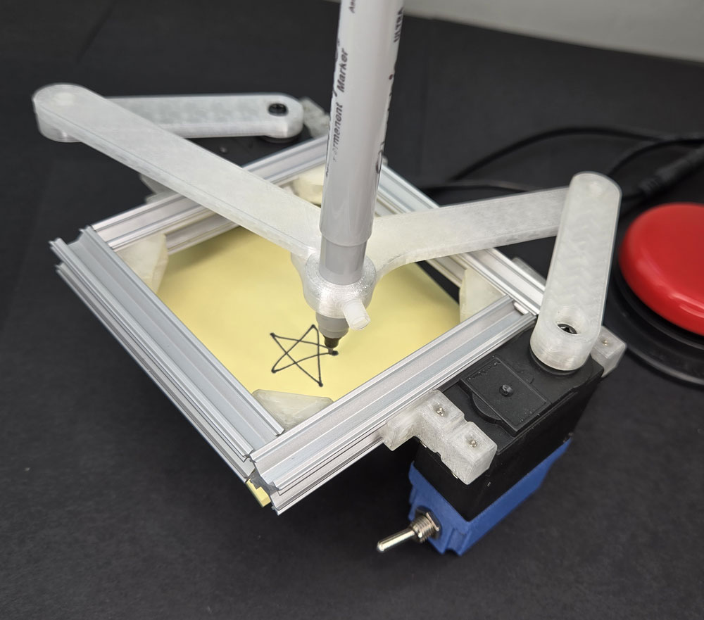
Core Idea: The assembled structure forms a five-bar linkage—two fixed ground links (T-slot frame pieces) and four moving links (L1-L4)—creating a closed kinematic chain where two motors can control end effector position throughout a curved workspace.
Why It Matters: Five-bar linkages are fundamental to industrial robotics, surgical systems, and prosthetic devices because they provide precise position control with minimal motors, making them efficient and cost-effective for real-world applications.
Discussion Prompts to Consider:
- "Before we start moving the servos, can you trace the path of connected parts from one servo to the drawing point and back to the other servo? Why do we need both paths to meet?"
- "What would happen to the system if we removed L3? Would we still be able to control where the pen goes?"
- "How is this different from the pan-and-tilt system you built previously? What does this linkage give us that separate axes don't?"
Watch For: Students may initially count only the moving links (L1-L4) and miss that the two fixed T-slot pieces also count as "bars" in the linkage. Reinforce that linkage analysis includes all rigid connections in the system.
Moment 2: Inverse Kinematics Through Calibration
Student Guide Reference: Calibration Process section (determining servo angles for specific pen positions)
Core Idea: Working backward from a desired end position to determine required joint angles is called inverse kinematics—a fundamental challenge in robotics that often requires iterative problem-solving rather than direct calculation.
Why It Matters: Professional robots face this same challenge constantly, but use sophisticated algorithms to solve it instantly. Understanding the difficulty of this problem helps students appreciate both the complexity of robotic motion planning and why trial-and-error calibration is sometimes the most practical approach.
Discussion Prompts to Consider:
- "You're trying to get the pen to a specific dot. Why can't you just measure the distance and calculate the angles you need?"
- "What made the calibration process easier or harder? What strategies did you develop for finding the right angles faster?"
- "If you wanted the DrawBot to create smooth circles instead of straight lines between points, what additional information would you need to figure out?"
Extension Opportunity: Have students research how industrial robots solve inverse kinematics mathematically (trigonometry, matrix algebra), or explore how video game character animations handle the same problem when moving limbs to reach objects.
Moment 3: Coordinated Multi-Axis Control
Student Guide Reference: Step 18-19 (programming synchronized servo movements)
Core Idea: The DrawBot requires both servos to move to precise angles simultaneously, with their combined positions determining where the pen lands—this is coordinated control where neither servo alone achieves the goal, only their relationship matters.
Why It Matters: Most real-world robots require multiple motors working in coordination, from robotic arms assembling cars to surgical robots performing delicate procedures. Understanding how independent actuators must be orchestrated together is foundational to robotics and automation.
Discussion Prompts to Consider:
- "What happens if the LEFT servo moves to Point 2 before the RIGHT servo catches up? Why does the drawing look different?"
- "Look at your angle table—do you notice any patterns in how the angles change together as you move from point to point?"
- "How would you program the DrawBot to move more slowly and smoothly between points instead of jumping? What would need to change in the code?"
Demo/Visual Aid Suggestion: Show the DrawBot moving with only one servo active (comment out the other servo's angle commands) so students can see how neither servo alone creates the intended path—only their combination produces the star pattern.
Moment 4: Accessible Mathematical Art
Student Guide Reference: Client profile and "The Bigger Picture" section
Core Idea: The DrawBot preserves Maya's ability to explore mathematical patterns and geometric art by removing the physical burden of manual drawing, demonstrating how assistive robotics can maintain creative agency when manual dexterity becomes limiting.
Why It Matters: Assistive technology is most powerful when it enables people to pursue their passions and interests, not just perform basic tasks. Maya's DrawBot isn't about writing—it's about preserving her identity as someone who explores the intersection of math and art.
Discussion Prompts to Consider:
- "How does the DrawBot specifically address Maya's needs? What would happen if we only focused on making drawing 'easier' rather than removing the physical strain entirely?"
- "Maya loves exploring the connection between math and art. How does having precise, repeatable robotic control actually enhance that exploration compared to freehand drawing?"
- "What other creative or academic pursuits might become inaccessible to people with limited hand strength? How could similar robotic systems help?"
MATERIALS & PREPARATION
WHAT STUDENTS NEED
Kit components (from student guide Step 1):
- Gussets, T-slot mounts, linkages L1-L4
- T-slot frames, M5 set screws
Tools from previous kits (Step 2):
- Tap and handle, screwdrivers, Allen keys
Electronics:
- Two Smart Servos
- Dual Power Pack
- Dual 3.5mm Jack
- Test Button or assistive button
- Coding cable
Consumables:
- Paper (sticky notes work well)
- Writing instruments (markers, pencils)
Safety equipment:
- Safety glasses for tapping threads
What You Need to Prepare
- Pre-build one DrawBot to identify assembly challenges, test code, and determine optimal paper/marker combinations
- Prepare visual aids for five-bar linkages (photos of industrial robots, surgical systems, or prosthetic arms using similar mechanisms)
- Review student guide pages covering linkage assembly (Steps 3-17) and calibration process
- Set up workstations with organized T-slot components, screws sorted by size, and adequate space for frame assembly
- Test dual servo code on both LEFT and RIGHT servos to verify synchronization timing
- Prepare graph paper or coordinate grids for students to plan custom geometric patterns
- Choose assessment approach (see page 5)
- Select extension activities if time allows (see page 4)
Quick Troubleshooting Reference
| If students struggle with... | First, check... | Then try... |
|---|---|---|
| T-slot pieces won't slide together | Set screws protruding too far into slots | Back off all set screws another 2-3 turns before assembly |
| Linkages binding or moving stiffly | Over-tightened set screws at pivot points | Loosen pivot screws slightly—linkages should swing freely with minimal resistance |
| Servos not moving together | One servo coded incorrectly or power issue | Verify both servos show same LED colors; check Dual Power Pack connections; confirm code uploaded to both devices |
| Pen position drifts during drawing | Loose set screws in linkages or T-slot | Re-tighten frame assembly first, then linkage pivots while maintaining free movement |
| Inverse kinematics calibration frustration | Trying to calculate angles mathematically | Emphasize trial-and-error is the correct approach; suggest systematic grid search pattern |
TEACHING PROGRESSION
The student guide provides detailed assembly and content. Use this framework to structure your instruction around their independent work.
1. ENGAGE
How can mathematical art exploration become inaccessible when physical limitations interfere with creative expression?
Learning Focus: Students understand Maya's need for accessible mathematical art creation and identify how physical limitations can restrict creative expression.
Suggested Activities
Client Introduction:
- Have students read Maya's profile and challenge description
- Consider: Brief sketching activity where students draw geometric patterns for two minutes, then discuss hand fatigue—how would extended sessions feel with arthritis?
- Discuss: What makes geometric art appealing? Why is precision important for mathematical patterns? How does pain interfere with creative focus?
Problem Framing:
- Guide students to articulate: "Maya needs a way to create precise geometric patterns without manual drawing because juvenile arthritis causes hand fatigue and joint pain during extended drawing sessions"
- Connect to broader accessibility: Who else might benefit from automated drawing systems? (tremor conditions, fine motor challenges, fatigue disorders)
- Preview: How might robotic precision actually enhance mathematical art exploration beyond just reducing physical strain?
Formative Assessment Ideas
- Can students explain why precision matters specifically for Maya's mathematical art interest?
- Do they recognize that the solution needs to remove physical burden entirely, not just make drawing "easier"?
- Do they see connections between this challenge and previous assistive technology projects?
Standards Connection: Primary: HCD #1 (Problem Framing), STEL 1Q (Research to inform design), STEL 7Z (Human-centered design principles), ETS2 (Technology's role in addressing human needs)
2. EXPLORE
How do two servos working together create positioning capabilities that neither could achieve alone?
Learning Focus: Students develop skills in rigid frame construction, linkage assembly, and multi-servo coordination while making observations about how mechanical geometry constrains motion.
Facilitation Approach
Before Building:
- Students complete Steps 1-2 (inventory components, gather tools)
- Consider: Have students predict how two servos will control one drawing point—sketch their hypothesis
- Review safety for tapping threads and working with moving linkages
During Building:
- Students follow detailed assembly in Steps 3-17
- Use Essential Teaching Moment #1 (Step 5-8): Pause after frame assembly to discuss five-bar linkage structure
- Circulate during Steps 11-14 (servo angle setup) to ensure proper 0-degree calibration—this is critical for later accuracy
- Use Essential Teaching Moment #2 during calibration process: Observe problem-solving strategies for inverse kinematics
- Encourage documentation of calibration angles in organized tables
Testing Phase (Steps 18-19):
- Use Essential Teaching Moment #3: Observe synchronized motion and discuss coordination challenges
- Guide systematic observation: "Watch how the linkages move. Can you predict where the pen will go based on just one servo's position?"
- Consider: Data collection about workspace boundaries—where can the pen reach? Where can't it?
- Preview trade-offs between speed, precision, and workspace size
Formative Assessment Ideas
- Are students properly squaring the T-slot frame and checking rigidity?
- Can they explain why both servos must be at specific angles simultaneously?
- Are they systematically recording calibration angles rather than trying random combinations?
- Do they troubleshoot mechanical binding before assuming code problems?
Standards Connection: Primary: CAD 1.2 (Assembly and fabrication), CAD 2.4 (Geometric analysis), CAD 3.3 (Assembly modeling), STEL 2M (Systems—inputs, processes, outputs), NGSS Practice 3 (Planning investigations), CSTA (Hardware/software integration)
3. EXPLAIN
Why is determining servo angles from a desired position (inverse kinematics) fundamentally more challenging than predicting position from known angles (forward kinematics)?
Learning Focus: Students connect their hands-on calibration experience to robotics concepts including five-bar linkages, inverse kinematics, and trajectory planning.
Suggested Sequence
Process the Experience:
- Reflection: "What was most challenging about the calibration process? Why couldn't you just measure distances and calculate the angles you needed?"
- Introduce key vocabulary using completed DrawBot as reference: five-bar linkage, end effector, inverse kinematics, forward kinematics, workspace, trajectory, interpolation
- Consider: Use the "Understanding the Robotics" section from student guide as discussion framework
Explore Core Concepts:
Five-Bar Linkage Systems:
- Use content from student guide's "Five Bar Linkages in Real Robotics" section
- Have students identify all five bars in their system (including the two fixed T-slot pieces)
- Provide visual aids: Show industrial pick-and-place robots, surgical robots, or prosthetic arms using five-bar linkages
- Discuss advantages: Two motors control position anywhere in workspace; efficient and cost-effective
Inverse Kinematics vs. Forward Kinematics:
- Use content from "The Challenge of Inverse Kinematics" section
- Ground abstract ideas: "Forward kinematics is easy—set these angles, see where pen goes. Inverse kinematics is hard—want pen here, figure out what angles get it there"
- Connect to calibration frustration: Professional robots use complex math (trigonometry, calculus, linear algebra) to solve this instantly, but the underlying problem is exactly what students experienced
- Consider: Compare to everyday inverse problems (working backward from desired outcomes)
Trajectory Planning and Smooth Motion:
- Use "From Straight Lines to Smooth Curves" section
- Discuss: Your DrawBot currently jumps between angles, creating straight line segments. Smooth curves require gradually changing angles over time (interpolation)
- Introduce splines and Bézier curves as mathematical tools for smooth path planning
- Connect to familiar applications: These same concepts appear in graphic design software, animation, and car body design
Teaching Strategies to Consider:
- Think-pair-share: "Explain inverse kinematics to your partner using your calibration experience as the example"
- Annotate the DrawBot: Have students label the five bars, identify the end effector, and mark the workspace boundary
- Compare/contrast: How is this different from the pan-and-tilt system where each servo controlled one axis independently?
- Identify examples: Where have students seen coordinated multi-axis motion in everyday life?
Connect to User Needs:
- Use Essential Teaching Moment #4: Discuss how precise, repeatable robotic control serves Maya's specific needs
- Analyze design trade-offs: Workspace size vs. mechanical complexity; speed vs. precision; calibration time vs. accuracy
- Consider optimization: How might the DrawBot be customized for different paper sizes or different types of patterns?
Formative Assessment Ideas
- Can students correctly identify all five bars in the linkage system?
- Can they explain inverse kinematics using the calibration process as an example?
- Do they understand why two servos working together can reach any point in a workspace?
- Can they articulate how robotic precision enhances Maya's mathematical art exploration?
Standards Connection: Primary: CAD 1.4 (Explain technical solutions), CAD 2.4 (Geometric analysis and motion paths), HCD #2 (Stakeholder communication), NGSS Cross-Cutting Concepts (Systems and system models, Cause and effect), STEL 7S (Human factors in design), STEL 3B (Simple technologies forming complex systems)
4. ELABORATE
How can we transfer five-bar linkage principles to new applications or optimize the DrawBot's performance for different creative goals?
Learning Focus: Students apply robotics concepts to new contexts, optimize designs, or explore advanced motion planning challenges.
Extension Menu
Choose based on available time, student readiness, and learning priorities
Option A: Custom Geometric Pattern Design
What Students Do: Design and program a custom geometric shape (triangle, square, hexagon, mandala, fractal pattern) by completing calibration tables for their chosen design
Skills Developed: Geometric reasoning, systematic calibration, pattern planning, mathematical visualization
Time Estimate: 45-60 minutes for calibration and testing
Option B: Smooth Curve Implementation
What Students Do: Modify code to interpolate between points, creating smooth curves instead of straight line segments by adding intermediate angle steps
Skills Developed: Computational thinking, algorithm design, trajectory planning concepts
Time Estimate: 60-90 minutes
Option C: Workspace Analysis and Optimization
What Students Do: Systematically explore and document the DrawBot's reachable workspace by testing grid positions and creating a visual map of accessible vs. inaccessible areas
Skills Developed: Spatial reasoning, data collection and visualization, understanding kinematic constraints
Time Estimate: 45-60 minutes
Option D: Assistive Technology Transfer Challenge
What Students Do: Identify another precision-positioning application that could use similar five-bar linkage systems and create a concept proposal (examples: adaptive eating assistance, laboratory sample handling, accessible craft tools)
Skills Developed: Analogical reasoning, design thinking, assistive technology awareness
Time Estimate: 30-45 minutes
Option E: Mathematical Art Research
What Students Do: Research geometric patterns in art, mathematics, or nature (Islamic geometric art, Spirograph patterns, fractals, Celtic knots) and analyze whether the DrawBot could recreate them
Skills Developed: Research skills, pattern analysis, connecting mathematics to cultural contexts
Time Estimate: 45-60 minutes
5. Evaluate
How does the DrawBot demonstrate both mechanical precision and human-centered design principles that address Maya's specific needs?
5. EVALUATE: Demonstrating Learning
Learning Focus: Students demonstrate competency in multi-axis robotic systems, inverse kinematics problem-solving, and human-centered design reasoning.
Recommended Assessment: Technical Demonstration with Explanation
What Students Do: Successfully build, calibrate, and program the DrawBot to create a geometric pattern (star provided or custom design), then explain the robotics principles at work
What You Assess:
- Assembly Quality: Rigid frame construction, proper linkage attachment, free movement without binding
- Calibration Process: Systematic approach to determining servo angles, organized documentation in angle tables
- Programming Accuracy: Both servos synchronized correctly, pattern drawn as intended
- Conceptual Understanding: Verbal or written explanation of five-bar linkages, inverse kinematics, and how the system addresses Maya's needs
Evidence: Completed and functional DrawBot + angle calibration table + drawing output + explanation (3-5 minutes verbal or 1-2 page written)
Alternative Assessment Options
Option 2: Design Portfolio Documentation
Create comprehensive documentation including assembly photos, calibration process notes with angle tables, code with annotations, reflection on inverse kinematics challenges, and connection to Maya's specific needs
Time Required: Built throughout lesson; 20-30 minutes for final reflection and organization
Option 3: Robotics Concept Presentation
Present the DrawBot to an audience while explaining five-bar linkage principles, demonstrating inverse kinematics calibration, discussing real-world applications, and connecting to human-centered design for Maya
Time Required: 30 minutes preparation, 5-7 minutes presentation per student/group
Reflection Prompts
Choose 2-3 based on your learning priorities
- Process: What was your biggest challenge during calibration? What strategies did you develop for finding the right servo angles more efficiently?
- Concept: Explain inverse kinematics to someone who hasn't built a DrawBot. Why is it harder than forward kinematics?
- Impact: How does robotic precision specifically enhance Maya's ability to explore mathematical art? What does the DrawBot enable that manual drawing with assistive grips couldn't?
- Transfer: Where else have you seen multiple motors working together to control one output? How is your DrawBot similar to or different from those systems?
- Growth: What surprised you most about building a multi-axis robot? What do you want to learn more about in robotics or assistive technology?
Standards Connection: Assessment should provide evidence of: CAD 1.1-1.4 (Technical vocabulary, assembly, documentation, explanation), HCD #2, #8, #9 (Communication, iteration, documentation), NGSS Practices (Planning investigations, using models, constructing explanations), STEL 7Z (Human-centered design principles), CSTA (Hardware/software integration and problem-solving)
ASSESSMENT RUBRIC
| Criteria | Developing | Proficient | Advanced |
|---|---|---|---|
| Assembly Quality | Frame looseness or binding affects motion; linkages attached incorrectly; servos not properly mounted | Frame rigid and square; all linkages move freely; servos securely mounted; connections tight without over-tightening | Exceptional attention to mechanical precision; optimized assembly for minimal play; thorough testing of all pivot points before finalizing |
| Calibration Process | Incomplete angle table; trial-and-error without documentation; difficulty explaining process | Complete angle table with systematic documentation; pattern draws recognizably; can explain calibration approach | Systematic, efficient calibration strategy; precise angle documentation; pattern draws with high accuracy; identifies and resolves calibration drift |
| Programming Accuracy | Code errors prevent operation; servos not synchronized; timing issues cause incomplete patterns | Both servos programmed correctly; synchronized motion; pattern completes as intended; proper LED indicators | Clean, well-commented code; optimized timing; smooth coordinated motion; creative enhancements to base code |
| Five-Bar Linkage Concept | Identifies some parts but cannot explain how linkage works as system; misunderstands relationship between servos and pen position | Correctly identifies all five bars; explains how two servos control pen position; understands basic closed kinematic chain concept | Sophisticated explanation of linkage geometry; analyzes how link lengths constrain workspace; connects to real-world robotic systems with specific examples |
| Inverse Kinematics Understanding | Confusion between forward and inverse kinematics; cannot explain why calibration is necessary | Clearly explains inverse kinematics as working backward from desired position to required angles; connects calibration experience to concept | Explains mathematical complexity of inverse kinematics; discusses why trial-and-error is practical approach; articulates how professional robots solve this computationally |
| User-Centered Reasoning | Mentions that DrawBot helps Maya; limited understanding of specific needs | Explains how robotic precision addresses Maya's specific needs for mathematical art without physical strain; connects features to user benefits | Analyzes how DrawBot preserves Maya's creative identity; discusses trade-offs in design choices; proposes thoughtful customizations for her specific context; understands broader accessibility implications |
CONNECTIONS & CONTEXT
Learning Sequence
What Students Already Know (from previous kits):
- Servo control and programming in CircuitPython (all previous kits)
- Coordinating multiple servos with dual power and button systems (Dual Servo Kit, Pan & Tilt Kit)
- Mechanical linkages and motion transformation (Dice Roller, Adaptive Grip)
- T-slot framing and rigid assembly methods (Gear Systems Kit)
- Human-centered design process and client-focused problem-solving (all kits)
What's New in This Kit:
- Five-bar linkage systems as closed kinematic chains
- Inverse kinematics problem-solving through calibration
- Coordinated multi-axis control where neither servo alone determines output
- End effector positioning in a two-dimensional workspace
- Systematic calibration and angle table documentation
Where This Leads (in future applications):
- Advanced robotics projects with six or more axes
- CNC machining and laser cutting (similar inverse kinematics challenges)
- Computational approaches to solving inverse kinematics mathematically
- Trajectory planning and motion smoothing algorithms
- Industrial automation and manufacturing systems
Cross-Curricular Connections
Mathematics
- Coordinate systems and Cartesian planes appear naturally during calibration—students map servo angle combinations to pen positions in 2D space
- Geometric properties of patterns—symmetry, angles, side lengths—inform design choices when creating custom shapes
- Trigonometry and angle relationships can be explored by analyzing how linkage lengths and angles combine to determine pen position
- Graphing and data visualization when documenting workspace boundaries and creating reachable area maps
Science
- Newton's Laws of Motion demonstrated through linkage acceleration and momentum—why smooth motion requires gradual angle changes
- Forces and mechanical advantage in linkage systems—how link lengths affect force transmission and positioning accuracy
- Energy transformation from electrical (servo motors) to kinetic (linkage motion) to potential (pen position)
Social Studies
- History of automation and the industrial revolution—how automated systems changed manufacturing and accessibility
- Disability rights movement and assistive technology development—legal and social context for accessible tools (ADA, Section 504)
- Cultural geometric art traditions—Islamic geometric patterns, Celtic knots, Indigenous art—provide meaningful pattern design context
English/Language Arts
- Technical writing in calibration documentation and angle table creation—precision and clarity essential
- Persuasive writing in design proposals for alternative applications of five-bar linkage systems
- Vocabulary development with domain-specific terms from robotics and kinematics
ADDITIONAL RESOURCES
For Teachers:
- Student Guide: WagnerLabs.NET/SmartServo/
- 3D Printing Files: tinyurl.com/SS-STL-DRAW
- Code Snippets: tinyurl.com/SmartServoSnips
- Example Code (Star Pattern): tinyurl.com/ss-code-draw
- Visual aids suggestion: Search "five bar linkage robot" for industrial examples; "surgical robot kinematics" for medical applications
For Students:
- Assembly: Detailed instructions in student guide Steps 3-17
- Concepts: "Understanding the Robotics Behind Your DrawBot" section (pages covering five-bar linkages, inverse kinematics, trajectory planning)
- Calibration guidance: Calibration Process section with systematic angle-finding strategies
- Code: Complete LEFT and RIGHT servo code examples in student guide Step 18
Extension Reading/Resources:
- Inverse Kinematics: Age-appropriate explanations of how video game characters reach for objects or how robotic arms calculate joint angles
- Trajectory Planning: Articles about how CNC machines and 3D printers create smooth motion paths
- Bézier Curves: Interactive web demonstrations of how graphic design software creates curves from control points
- Assistive Robotics: Resources about robotic systems helping people with limited dexterity (feeding robots, dressing assistance, adaptive tools)
- Islamic Geometric Art: Exploration of mathematical patterns in cultural art traditions that could inspire DrawBot designs
COMPLETE STANDARDS ALIGNMENT
CAD Competencies
| Code | Competency | Where Addressed | How to Emphasize |
|---|---|---|---|
| CAD 1.1 | Technical vocabulary | Phase 2 (Building), Phase 3 (Explain) - Terms include five-bar linkage, end effector, inverse kinematics, forward kinematics, workspace, trajectory, interpolation, splines; Teaching Moments #1-3 | Have students create annotated diagrams labeling all components; use vocabulary in written calibration documentation; require technical terms in presentations |
| CAD 1.2 | Assembly/fabrication | Phase 2 (Building) - Steps 3-17 focus on rigid frame construction, linkage attachment, precise servo mounting | Observe proper tapping technique; check frame squaring before tightening; assess linkage pivot points for free movement; evaluate final assembly rigidity |
| CAD 1.3 | Technical documentation | Phase 2 (Calibration), Phase 5 (Evaluate) - Angle calibration tables are essential documentation; portfolio option emphasizes process recording | Provide templates for organized angle tables; emphasize clarity and completeness; model proper annotation of assembly photos |
| CAD 1.4 | Explain technical solutions | Phase 3 (Explain), Phase 5 (Evaluate) - Explaining five-bar linkage function, inverse kinematics process, how system serves Maya's needs | Use sentence frames for technical explanation; require connection between mechanical geometry and pen position; practice explaining to non-technical audiences |
| CAD 2.4 | Geometric analysis | Phase 2 (Building/Testing), Phase 3 (Explain) - Understanding how linkage lengths and angles constrain workspace; analyzing motion paths; Teaching Moment #1 | Explicitly discuss geometric constraints; have students predict workspace boundaries; analyze why certain positions are unreachable; connect link geometry to reachable area |
| CAD 3.3 | Assembly modeling | Phase 2 (Building) - T-slot frame, servo mounts, four linkages must be properly constrained; understanding mate relationships in mechanical assembly | Emphasize proper constraint at each connection point; discuss over-constraint vs. under-constraint; analyze degrees of freedom at each joint |
CSTA Computer Science Standards
| Code | Standard | Where Addressed | How to Emphasize |
|---|---|---|---|
| Computing Systems: Devices | Describe computing device parts and functions | Phase 2 (Building/Testing) - Understanding how microcontroller coordinates two servos simultaneously; dual power system; Teaching Moment #3 | Explicitly trace signal path from button through both microcontrollers to synchronized servo motion; discuss timing challenges |
| Computing Systems: Hardware & Software | Design projects combining hardware and software | Throughout - Entire DrawBot is integrated hardware/software system requiring calibrated mechanical assembly and synchronized code | Make integration explicit—show how code depends on mechanical calibration accuracy; demonstrate that neither hardware nor software alone creates desired outcome |
| Computing Systems: Troubleshooting | Systematically identify and fix problems | Phase 2 (Testing), troubleshooting table - Distinguishing mechanical binding from code timing issues; power connection problems | Guide systematic diagnosis: Is it mechanical? Electrical? Code? Teach students to isolate subsystems when troubleshooting |
| Algorithms & Programming: Control | Programming control structures | Phase 2 (Programming) - Coordinated servo angle commands; state management for button press; LED color indicators | Emphasize sequential nature of angle commands; discuss why timing (delays) matters for synchronized motion; modify timing to observe effects |
| Algorithms & Programming: Control | Complex control structures | Extension Option B - Implementing interpolation requires nested loops or functions generating intermediate angles | Guide students to break smooth motion into algorithmic steps; use pseudocode before implementation; discuss loop design for gradual angle changes |
HCD Skills & Tools
| Code | Skill/Tool | Where Addressed | How to Emphasize |
|---|---|---|---|
| HCD #1 | Problem Framing | Phase 1 (Engage) - Analyzing Maya's need for mathematical art access without physical strain; Teaching Moment #4 | Use multiple perspectives: What does Maya want to accomplish? What physical barriers exist? Why is precision important for mathematical exploration? Consider systemic accessibility challenges |
| HCD #2 | Stakeholder Communication | Phase 3 (Explain), Phase 5 (Evaluate) - Explaining how robotic precision serves Maya's specific creative needs; presentations connecting technical features to user benefits | Practice user-friendly language; focus on what the DrawBot enables (mathematical pattern exploration) rather than just what it does (draws shapes) |
| HCD #5 | Knowledge Development | Phase 2-3 - Learning inverse kinematics concepts through calibration experience; researching five-bar linkages | Make learning process visible—document questions that arise during calibration; celebrate productive struggle with inverse kinematics; connect hands-on experience to formal concepts |
| HCD #6 | Stakeholder Dialogue | Phase 1 (Engage), Teaching Moment #4 - Considering Maya's perspective; imagining feedback conversations about pattern preferences or workspace needs | Role-play: How would you ask Maya what geometric patterns interest her most? How would you gather feedback after she tests the DrawBot? |
| HCD #8 | Iteration Cycles | Phase 2 (Calibration), Extension Option A (Custom patterns) - Iterative calibration process is inherently about testing and refining; custom pattern design requires iteration | Emphasize that calibration trial-and-error is the correct engineering approach, not a sign of failure; document how each iteration improves accuracy |
| HCD #9 | Design Documentation | Phase 5 (Evaluate) - Angle calibration tables, assembly photos, code annotations, process reflection | Teach documentation as enabling reproduction—could someone else recreate your pattern using your angle table? Why does documentation matter in professional engineering? |
| HCD Tool 1.2 | Problem Statement | Phase 1 (Engage) - Precise problem statement guides entire design | Use template: "Maya needs a way to create precise geometric patterns without manual drawing because juvenile arthritis causes hand fatigue and joint pain during extended drawing sessions" |
SAMPLE ASSESSMENT RUBRIC
Performance Demonstration with Technical Explanation
| Criterion | Developing | Proficient | Advanced |
|---|---|---|---|
| Assembly Quality | Frame looseness or binding affects motion; linkages attached incorrectly; servos not properly mounted | Frame rigid and square; all linkages move freely; servos securely mounted; connections tight without over-tightening | Exceptional attention to mechanical precision; optimized assembly for minimal play; thorough testing of all pivot points before finalizing |
| Calibration Process | Incomplete angle table; trial-and-error without documentation; difficulty explaining process | Complete angle table with systematic documentation; pattern draws recognizably; can explain calibration approach | Systematic, efficient calibration strategy; precise angle documentation; pattern draws with high accuracy; identifies and resolves calibration drift |
| Programming Accuracy | Code errors prevent operation; servos not synchronized; timing issues cause incomplete patterns | Both servos programmed correctly; synchronized motion; pattern completes as intended; proper LED indicators | Clean, well-commented code; optimized timing; smooth coordinated motion; creative enhancements to base code |
| Five-Bar Linkage Concept | Identifies some parts but cannot explain how linkage works as system; misunderstands relationship between servos and pen position | Correctly identifies all five bars; explains how two servos control pen position; understands basic closed kinematic chain concept | Sophisticated explanation of linkage geometry; analyzes how link lengths constrain workspace; connects to real-world robotic systems with specific examples |
| Inverse Kinematics Understanding | Confusion between forward and inverse kinematics; cannot explain why calibration is necessary | Clearly explains inverse kinematics as working backward from desired position to required angles; connects calibration experience to concept | Explains mathematical complexity of inverse kinematics; discusses why trial-and-error is practical approach; articulates how professional robots solve this computationally |
| User-Centered Reasoning | Mentions that DrawBot helps Maya; limited understanding of specific needs | Explains how robotic precision addresses Maya's specific needs for mathematical art without physical strain; connects features to user benefits | Analyzes how DrawBot preserves Maya's creative identity; discusses trade-offs in design choices; proposes thoughtful customizations for her specific context; understands broader accessibility implications |
KEY VOCABULARY
Students should be able to define and use these terms:
A closed kinematic chain consisting of five rigid bars connected by joints, where two fixed bars provide a stable reference and moving bars create controlled motion of an end point.
Example: Your DrawBot has two fixed T-slot frame pieces and four moving links (L1, L2, L3, L4) that form a five-bar linkage system to control pen position.
The tool or device at the end of a robotic system that performs the intended task.
Example: The pen or marker attached to Link L4 is the end effector—it's what actually draws the patterns.
The process of determining what joint angles are required to position an end effector at a desired location; working backward from the goal position to figure out the necessary angles.
Example: During calibration, you practiced inverse kinematics by adjusting servo angles until the pen reached each dot on your pattern—you knew where you wanted the pen to go and figured out what angles got it there.
The process of calculating where an end effector will be positioned based on known joint angles; working forward from angles to determine position.
Example: When you set both servos to specific angles and observe where the pen ends up, you're using forward kinematics.
The complete area or volume that an end effector can reach given the mechanical constraints of the robotic system.
Example: Your DrawBot's workspace is limited by the lengths of the linkages—the pen can only reach positions within a specific curved area on the paper.
The path that an end effector follows as it moves from one position to another.
Example: Your DrawBot's trajectory is currently made of straight line segments between points; smooth curves would require a more complex trajectory.
The process of calculating intermediate values between two known values to create smooth transitions.
Example: To make your DrawBot draw smooth curves instead of straight lines, you would need to interpolate servo angles—gradually change from one angle to another through many small steps.
Operating multiple motors or actuators together in a synchronized way where their combined movements achieve a goal that neither could accomplish alone.
Example: Your DrawBot uses coordinated control—both servos must move to precise angles at the same time to place the pen at the intended position.
The process of adjusting or documenting the relationship between input values (like servo angles) and output results (like pen position) to ensure accuracy.
Example: You calibrated your DrawBot by testing different servo angle combinations and recording which angles placed the pen at each point of your star pattern.
A smooth mathematical curve defined by control points, commonly used in computer graphics and robotics for path planning.
Example: Professional drawing robots often use splines to create smooth, flowing curves between points instead of the straight line segments your DrawBot currently draws.
A specific type of smooth curve defined by control points, widely used in graphic design software and robotic path planning.
Example: When you draw curves in design software, you're often creating Bézier curves—the DrawBot could use similar mathematical concepts to create smooth geometric patterns.
A mechanical system where links form a closed loop with no free ends, creating constrained but precise motion.
Example: Your DrawBot's five-bar linkage is a closed kinematic chain—you can trace from one servo through the links and back to the other servo in a complete loop.